Home  /  BIM and ARCHICAD   /  Conditional Operators… aka Graphic Operators… aka POST 100

Conditional Operators… aka Graphic Operators… aka POST 100

(note: if you read this before 11 pm on Sunday June 19th, 2011, you should reread it as I’ve made some important updates)

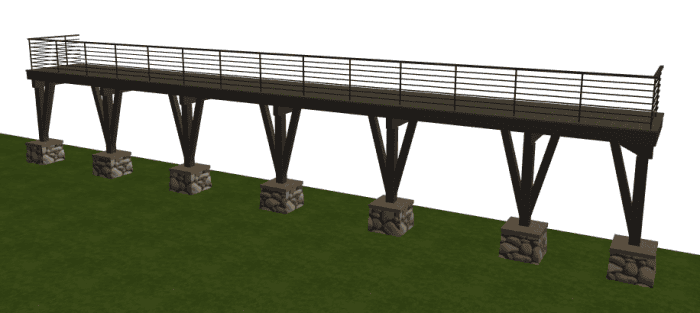
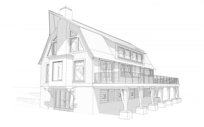
In many 2D drawings (whether done by hand or flatcad) parts of objects are left undrawn for clarity. Railings, for instance, are cut in front of elevations to better show what’s beyond. How do you do that in ArchiCAD without completely turning off the railing and adding it partially back in 2D or doing some weird slicing of objects (for instance by making the railing in 3 parts with 1 part on a separate layer so that it can be turned off). Options like that are doable, but are neither pretty nor supportive of the BIM workflow. I would rather have a solution that doesn’t interfere with proper modeling techniques.

Solid Element Operations (SEO) and smart use of layers, layer combinations, priority numbers and layer intersection groups provide a solution. Layer intersection groups, layers, and layer combinations all deserve a post unto themselves (so I’ll only talk briefly about those). The operators are beams with a beam priority number of 1. The targets are columns and beams with higher priorities. When the layer intersection groups are the same, the beam priority trumps the SEO, hence the targets appear because the operator has lower priority. When the layer intersection groups are different, the beam priorities have no effect and the SEO works. So this suggests that this trick will work with beams, columns, and walls, but not slabs, roofs, and objects which don’t have priority numbers.

Now for an example of a conditional graphic operator:
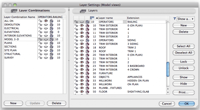
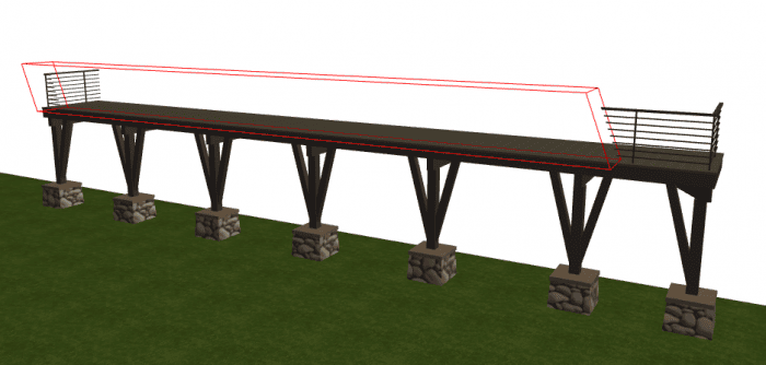
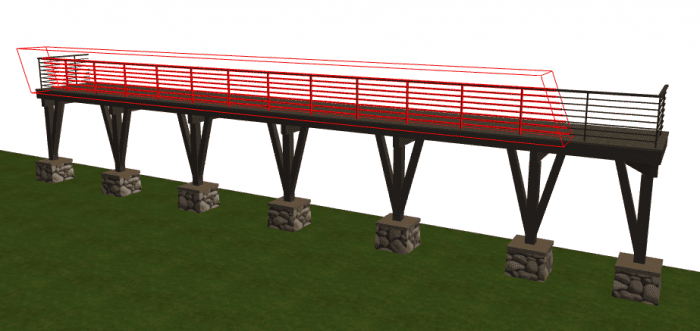
In the ELEVATIONS layer combination, the OPERATORS.RAILING layer is off and the intersection group is set to 0. In the MODEL 3-D layer combination, the OPERATORS.RAILING is off and the intersection group is set to 10. The operator remains hidden in both layer combinations, but only cuts the railing (which is on TRIM EXTERIOR. 0 (ON PLAN) and TRIM EXTERIOR.4) when the intersection groups DON’T match. In this example, the operation is only active on the ELEVATIONS layer combination.

The operator is visible and the intersection group is set to 0.

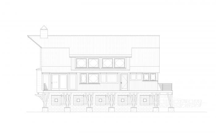
Model only in elevation with ELEVATION  layer combination. That’s right, everything in this image is modeled. NO 2D.

The operator is visible and the intersection group is set to 10.

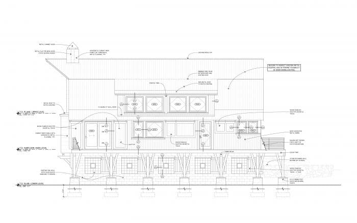
Model and 2D in elevation with ELEVATION layer combination (this is what appears in the construction documents)

The operator is not visible and the intersection group is set to 10.

3D Document with MODEL 3-D layer combination (this also appears in the Construction Documents)

Two caveats: I haven’t seen how this works in ArchiCAD 15. I presume it will be the same, but with the enhancements to trimming commands I don’t want to assume anything. I’ll get v15 loaded up sometime in the next week or two and verify there’s no change. I’ve also found this trick to be a little finicky. In v14 (the only version I’ve tested it in), the model sometimes doesn’t update the SEO properly when switching between layer combinations. So I get instances when the railing still shows in elevation or remains cut in my 3D document. A quick review of effected drawings and a manual switching back and forth between layer combinations gets everything working. But be warned and double check everything is displaying correctly before printing. As this is probably not what layer intersection groups and priority numbers are supposed to be used for, I don’t imagine this glitch is much known by Graphisoft or high on the ‘to fix’ list. And that’s okay. I’d rather Graphisoft focus on more important things.

06/21/11 update: my first explorations with v15 suggest that this trick still works if the operator is a beam and the targets are columns and walls, but no longer if the targets are beams. I’ve got more research to do.

06/26/11 update: Here’s a post that takes advantage of this behavior for a different purpose.

Comments

  • June 19, 2011
    reply

    Jared –

    This is brilliant! I had no idea that SEO were conditional based on layer intersection groups.

    Two questions:

    Have you tested this on earlier versions, going back to AC10?

    Also, what is the best way to make sure all is good before printing? I’d be concerned if refreshes are not consistent and automatic when you Rebuild the drawings on the sheets.

    Eric

  • June 19, 2011
    reply

    Karl Ottenstein

    I cannot reproduce this behavior consistently with a variety of SEOps, Jared – e.g., a simple roof trim. I have a feeling you’ve come across a bug rather than a feature.

    As far as I know, the intersection group number should have no effect on the behavior of solid element ops…

  • June 20, 2011
    reply

    Daniel

    Beautiful drawings!
    Are thos sliding shutters on the lower level a custom object? How do you achieve the modelling detail in the hardware for example?

  • July 5, 2011
    reply

    Scott Graham

    Great trick! In general, have you found working with beam & column handrail constructions to be more effective than GDL objects?

    I’ve been experimenting with this in AC15, and it seems hit-or-miss with the beams. I’ve somehow managed to make the Operator beam cut into one Target beam, but not multiple beams. Had any breakthroughs?

  • August 3, 2012
    reply

    Patrick

    This is a cool way to deal with 3d vs 2d views. In our office we never use stock library parts for things like railings or exterior ornamental components.
    We either use beams & columns w/ the top beam being the only one visible in plan views.
    Another option I have gone with a few times is to just save the created (beam/column) railing as a gdl object, then edit the 2d script to only show the outlines.

  • November 2, 2012
    reply

    HI

    I have a rather off-topic question!
    In the sceond elevation picture with all the labeling stuff how did you do the multi-leader that represent the same material?
    Did you do it by 2D work or with some special leader type?

    best regards
    Costas Issigonis

  • November 5, 2012
    reply

    thanks

    for the superfast answer!!

    I am aware about masterscript multi leader,but
    even thought it does what I almost want it does not do it in the way I would like to!!
    I would like to have a leader that can have multiple arrows and a circle around the text instead of the usual box!So I can just put the number of the material instead of the material itself!I think this way an elevation it is less “stressed” with all this text around it!

    best regards
    costas

  • January 27, 2016
    reply

    Juan

    Hi Jared, a question out of topic. How do you made the fills of the geometry appear a little clearer in comparation of the edges?

    Thanks!

Post a Comment