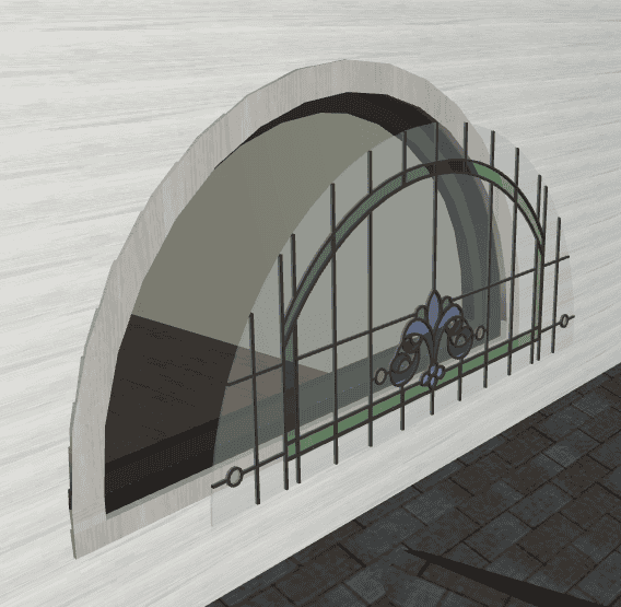
I recently had to model a Queen Anne house in ArchiCAD to produce some renderings for a client. It was a ton of fun. And I learned some cool tricks while modeling the various trim and ornamentation. I have to admit, of all the things I’ve done in ArchiCAD, this model is my favorite. Unfortunately I can’t share images of the entire house until the overall project is completed later this year. In the meantime, I’ll share some of the bits and pieces. Here’s how I modeled the stained glass window.

|
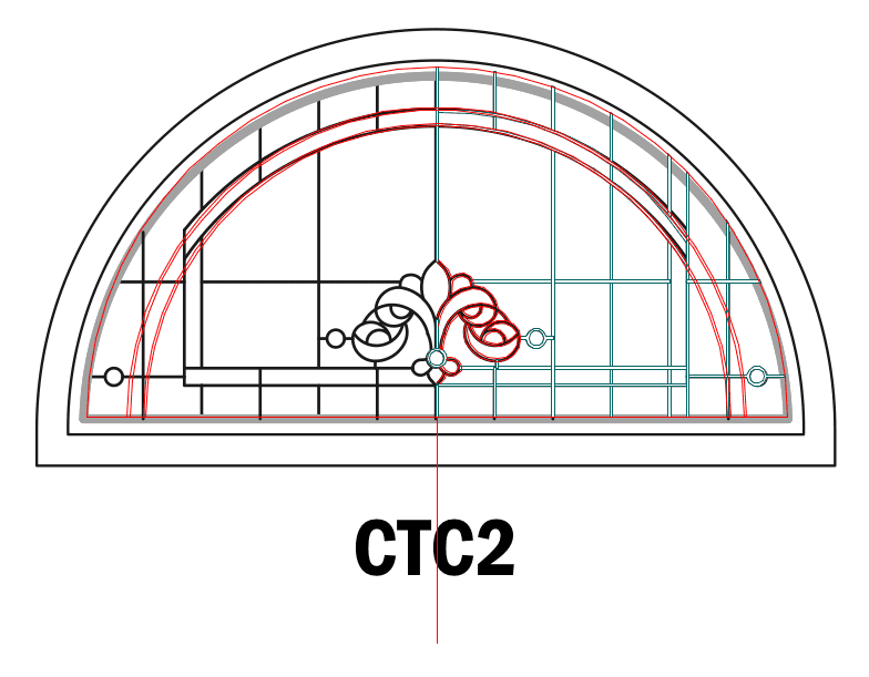
STEP 1: place a window and trace the extent of the stained glass. Move the traced shape away from the model so that you have a clear space to work with. It’s always a smart idea to move the 2D piece a known distance, say 50′ or 20 m.
 |
STEP 2: Overlay the shape of the window over the image you want to replicate and trace half.
 |
STEP 3: make fills (of the dividers/non-glass parts only), mirror a copy and use fill consolidation to make one large fill.
 |
STEP 4: Now that you have the divisions of the stained glass, magic wand in fills for all the glass pieces. I set each glass type to be a 25% fill with a pen color to match the final glass (for ease of 2D construction and visualization).
 |
STEP 5: Copy all the fills into the profile manager and make a complex profile (CP) for each glass color and one for the dividers. By placing all the fills into the profile manager at once, you can make sure that all the CPs line up. Just make sure to align the fills in the profile manager, copy them (to preserve their location), and then delete the extra fills before saving the CP. For the next color, duplicate the original CP, past all the fills, delete the ones you don’t need, save, & repeat.
 |
STEP 6: Make a new material for each color of glass. It’s easy enough to duplicate the standard glass, change the color, and decrease the transparency. For this window I created five colors of glass: purple, blue, green, pink, and a milky white. Assign the materials to the correct CP.
 |
STEP 7: Place one complex profile (I used the beam tool, with a beam length of 1/4″) and change the end material to match the CP material. Copy the beam. Change the CP and the end material to match the new CP. Paste the original beam (in original location). Repeat until you have all your pieces placed. Group the five Complex Profile beams that make up the stained glass. Make sure groups are enabled before heading to the next step.
 |
STEP 8: Move the grouped CPs into alignment in front of the window. In this example the stained glass sits right in front of the window glass, but still within the sash frame. Use a combination of plan, section, elevation, & 3D views, whatever makes sense to you. Do it all visually. It’s easier than math.
 |
STEP 9: View the finished stain glass in the 3D window. Call over a coworker and geek out to ArchiCAD for a few minutes. Go home and show off your modeling skills to your spouse.
Another route would be to build the stained glass out of slabs and save it as a custom window sash or custom window. In that case you’d use slabs instead of fills in steps 3 and 4, make and assign your custom glass materials, and then follow the standard steps to create a custom window sash or window. I think either process is valid, but describing the merits of each would make this post way too long.
14 thoughts on “Stained Glass Tutorial”
Very nicely written.
Thanks!!!
Nice!!
thanks
nice! i’d go with the slab version. If you have to change something afterwards, youre screwed in both methods 🙂
Changes are tough in both versions, but here’s the reasoning why I went with CPs instead of slabs… the decision to use CPs instead of a custom window sash or custom window came down to how I needed to work with the stained glass in the future, and how many there were in the project. If there were lots of these windows in a project, I’d probably make a custom window sash. But in this case there was only one. Also I expected that the window would change, probably on the fly in a meeting with the team lead or the client. CPs allow me to quickly tweak the colors by altering the materials, and would also allow me to more easily alter the pattern. To change the colors in a custom object would be a little more work.
Hi Jared. Thought I’d drop my slabified window link here if anyone is interested. It is useful where one has a weird whole window, or a window that needs a weird hole.
http://www.onland.info/archives/2006/10/slabified_window.php
We use CPs in the vast majority of what used to be slabify situations, but for something as complex as your glazing I might go the object route, to avoid glutting my CP list with Stained_part_1, Stained_part_2, … Stained_part_n. (Hm, I think you could save the finished glazing as an object and then delete up the CPs, since the script turns CPs into SPRISMs.)
It’s a pity that we can’t make that pattern with multiple fills in a single CP, and have the end materials read “naturally” rather than the dumb single end material of the beam element.
James, great post. I’m a huge fan of your blog and have read a lot of it, but I’ve never come across the post you linked to. And likewise I’ve used the technique you described many times (actually on this model I used that technique for a few custom window sashes), but I’ve never seen it explained so clearly. I also never thought to properly ID the parts for ease of tweaking the GDL. I need to remember that one!
You’re right though that this technique clutters the CP list. But it’s been a long time since I’ve had a project with an uncluttered CP list, so what’s a few more additions to the list? 🙂 And yes, if we could assign different end materials, that’d be so nice. Actually if all the CPs were condensed into one, and each had a different fill type so that they don’t merge, the pattern would read correctly in the Sketch Render Engine (for what that’s worth). There’s actually a firm in town that does all their elevations using the sketch rendering engine and they exploit that quark of CPs quite nicely for various elements.
Thanks again for the awesome link!
I am new to Archicad and want to learn more. I dont know to trace something. Did you import a picture or line drawing?
Regards
Christina
Christina, you could import either a picture, pdf, or a line drawing (dwg). The process is very similar, just drag the file from where it lives on your computer onto the ArchiCAD window you want it in. In this example I used a .jpeg I pulled off the internet. The drag and drop feature of adding external content to ArchiCAD is very easy and intuitive. It was a great addition when it was added in version 10.
Thanks for good info 🙂
Great to hear from James Murray! Onland (http://www.onland.info/) the Mother of All ArchiCAD blogs.
Pingback: Fun with Slabs – AKA Archi-treeStump and Slab ramps. Yes. Slab ramps. | Shoegnome
Pingback: ArchiCAD Video: Complex Profile Siding » Shoegnome
Pingback: Custom Empty Openings in ArchiCAD » Shoegnome